How to create a simple network topology
2025-09-12 Back to posts
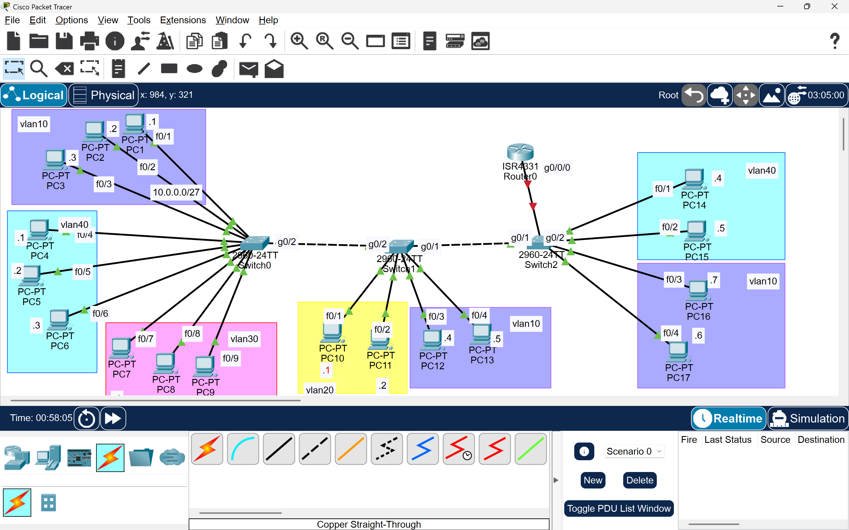
Building a VLAN Network Topology with Cisco Packet Tracer
🗒️ Introduction
In this tutorial, I’ll show you how to create a network topology with 17 PCs, 3 switches, and 1 router using Cisco Packet Tracer.
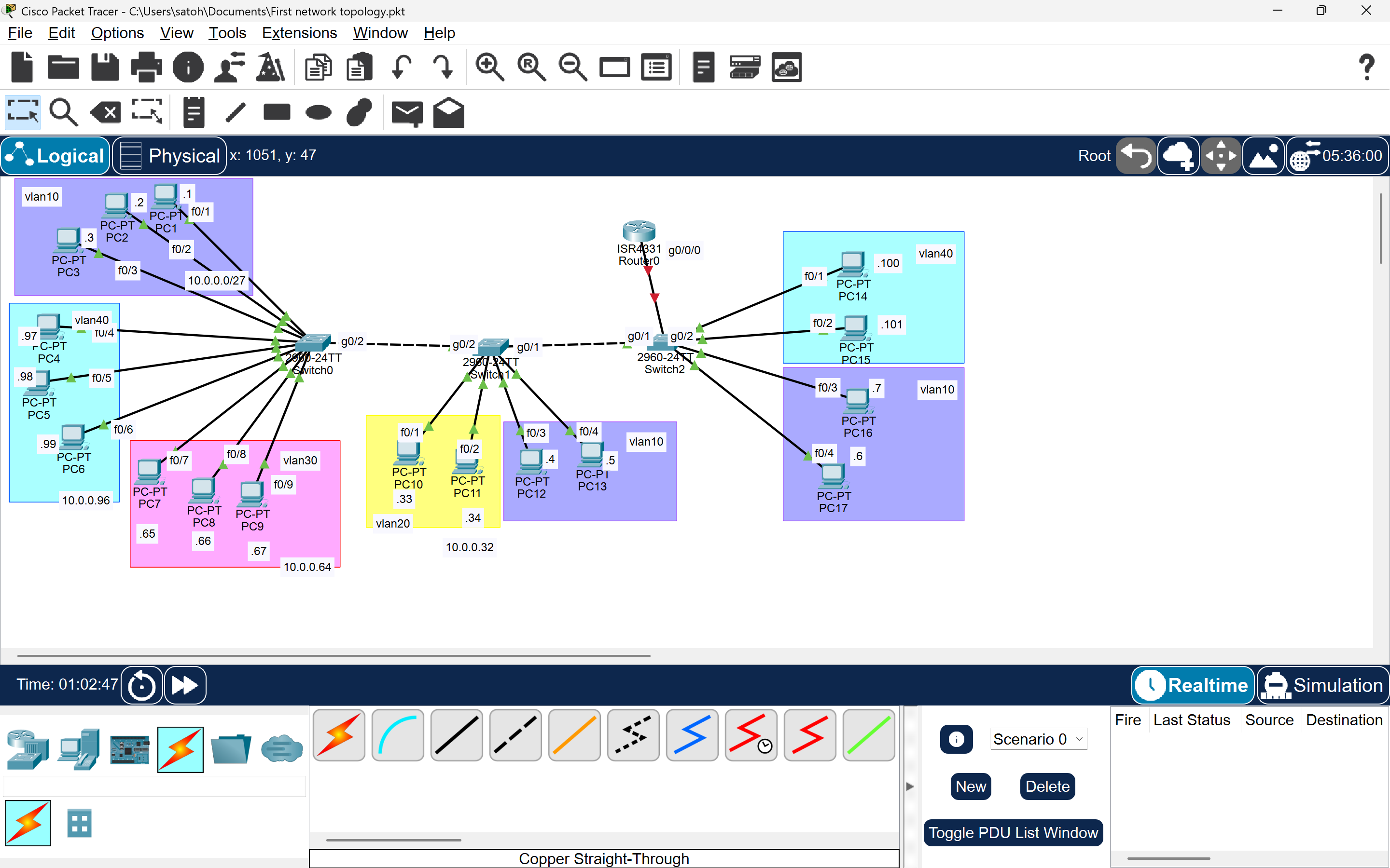
We’ll divide the network into four VLANs (VLAN10, VLAN20, VLAN30, VLAN40) and color-code each VLAN to make it visually clear.
Each VLAN has its own IP range, as shown below:
| VLAN | IP Range | Subnet Mask | Usable Hosts |
|---|---|---|---|
| VLAN10 | 10.0.0.1 – 10.0.0.30 | 255.255.255.224 (/27) | 30 |
| VLAN20 | 10.0.0.33 – 10.0.0.62 | 255.255.255.224 (/27) | 30 |
| VLAN30 | 10.0.0.65 – 10.0.0.94 | 255.255.255.224 (/27) | 30 |
| VLAN40 | 10.0.0.97 – 10.0.0.126 | 255.255.255.224 (/27) | 30 |
We’ll configure each PC with:
- IP Address
- Subnet Mask
- Default Gateway
After configuring the PCs, we’ll move on to the switches and router-on-a-stick setup.
Step 1: Create the Network Topology
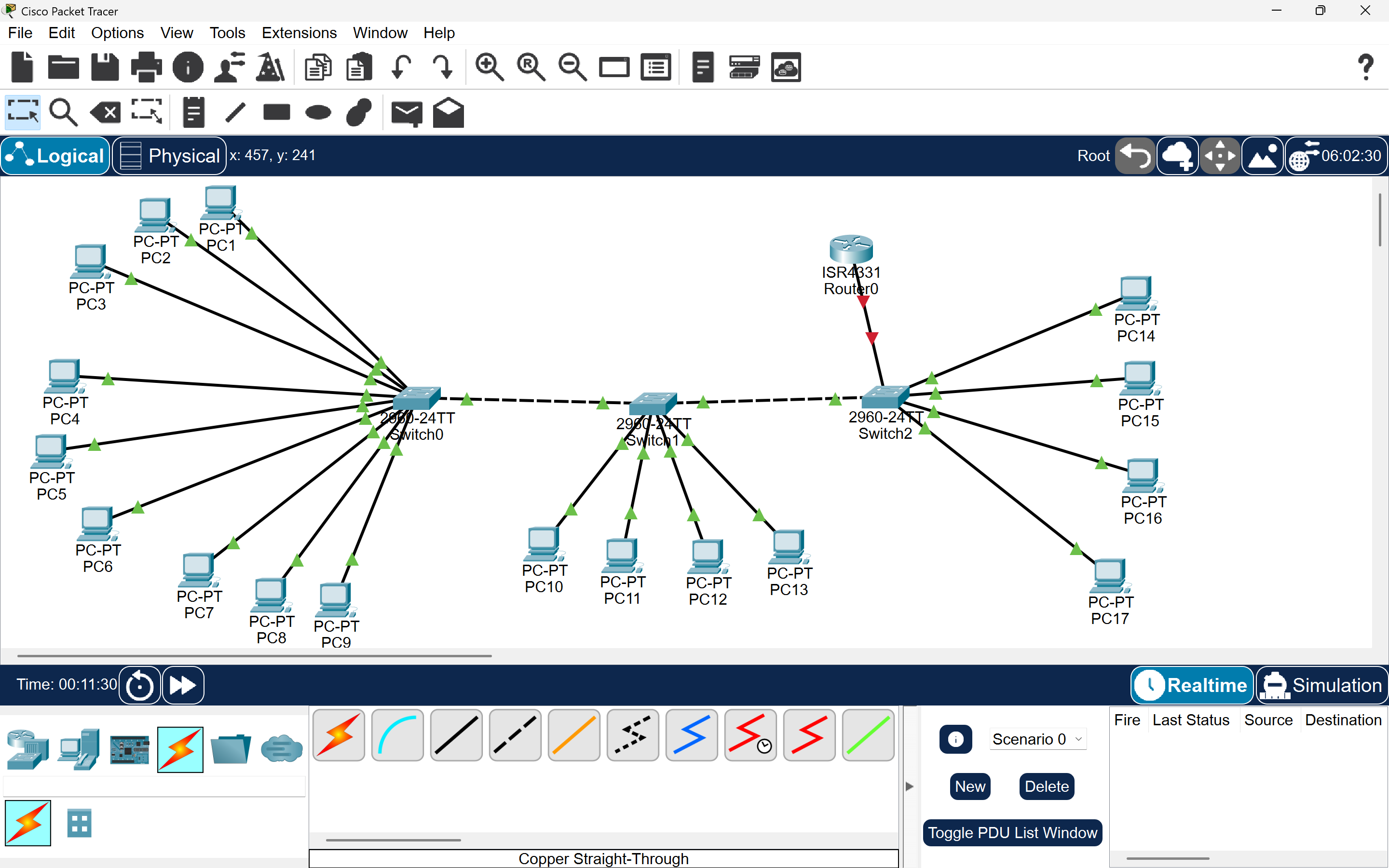
Drag and drop:
- 1 Router
- 3 Switches (SW1, SW2, SW3)
- 17 PCs
Then connect:
- PCs → Switches
- SW1 ↔ SW2 ↔ SW3
- SW1 ↔ Router (R1)
Step 2: PC Configuration
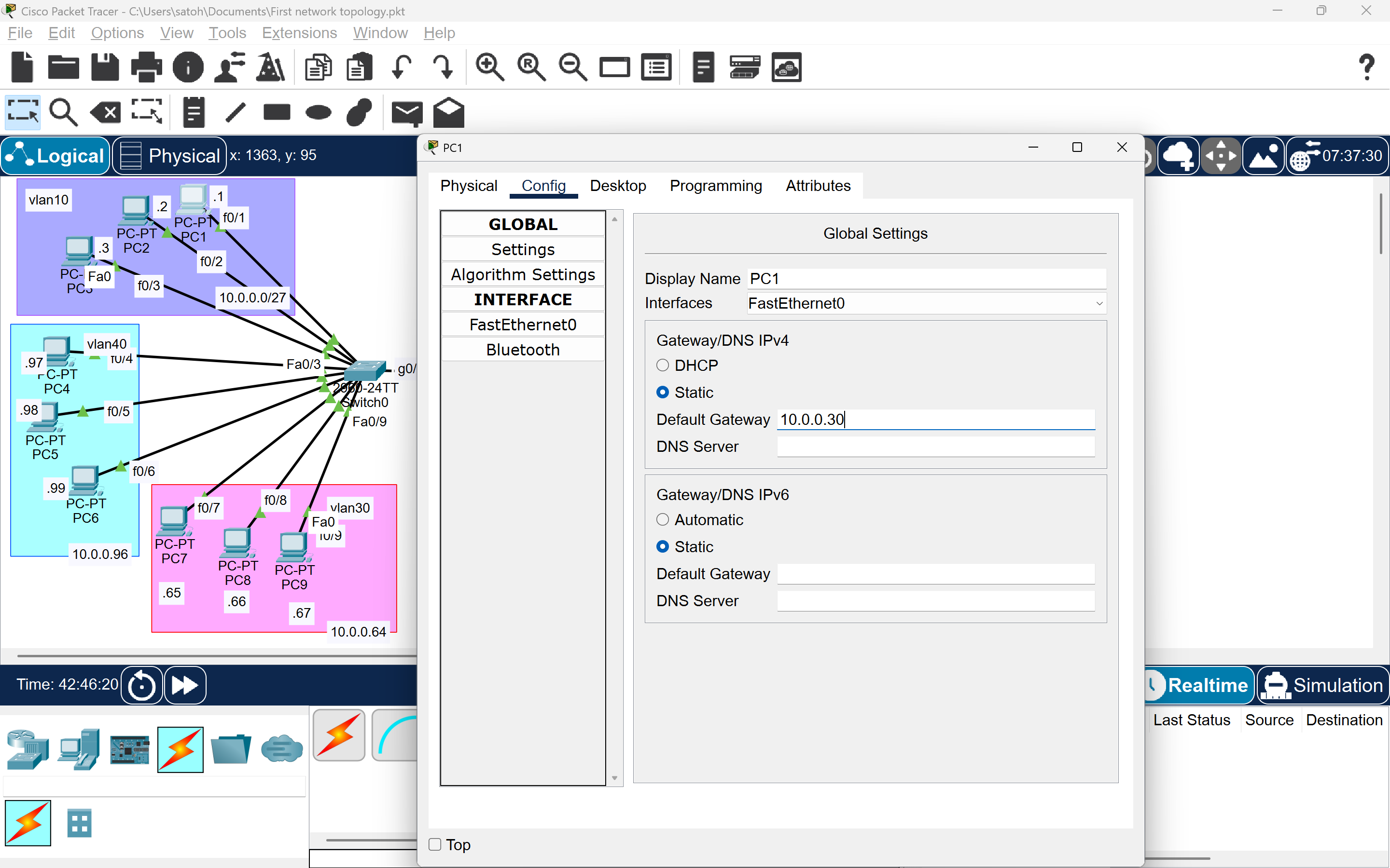
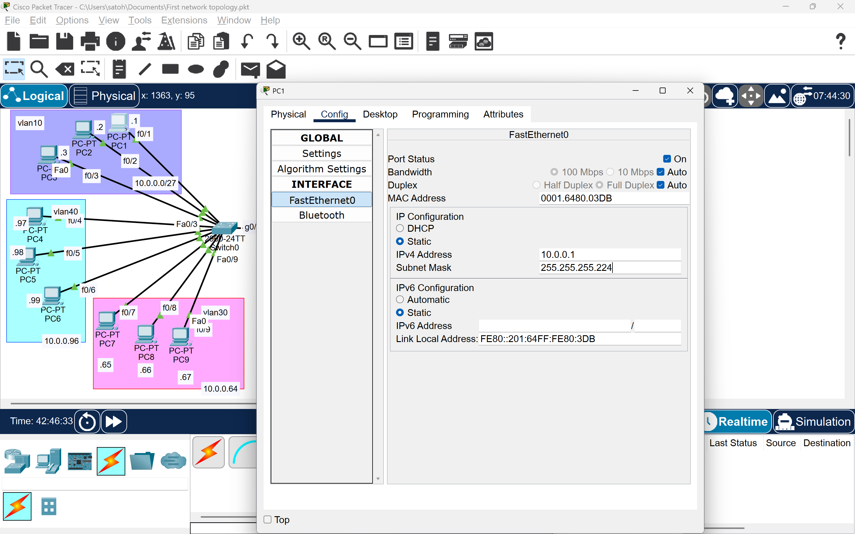
For each PC:
- Go to Desktop → IP Configuration
- Set:
- IP Address (based on VLAN range)
- Subnet Mask:
255.255.255.224 - Default Gateway (e.g.
10.0.0.30for VLAN10)
Repeat for all 17 PCs.
Step 3: Configure the Switches
We’ll start with SW1, then repeat similar steps for SW2 and SW3.
-
Change Hostname:
Switch> enable Switch# configure terminal Switch(config)# hostname SW1 -
Create VLANs:
SW1(config)# vlan 10 SW1(config-vlan)# name v10 SW1(config)# vlan 20 SW1(config-vlan)# name v20 SW1(config)# vlan 30 SW1(config-vlan)# name v30 SW1(config)# vlan 40 SW1(config-vlan)# name v40 -
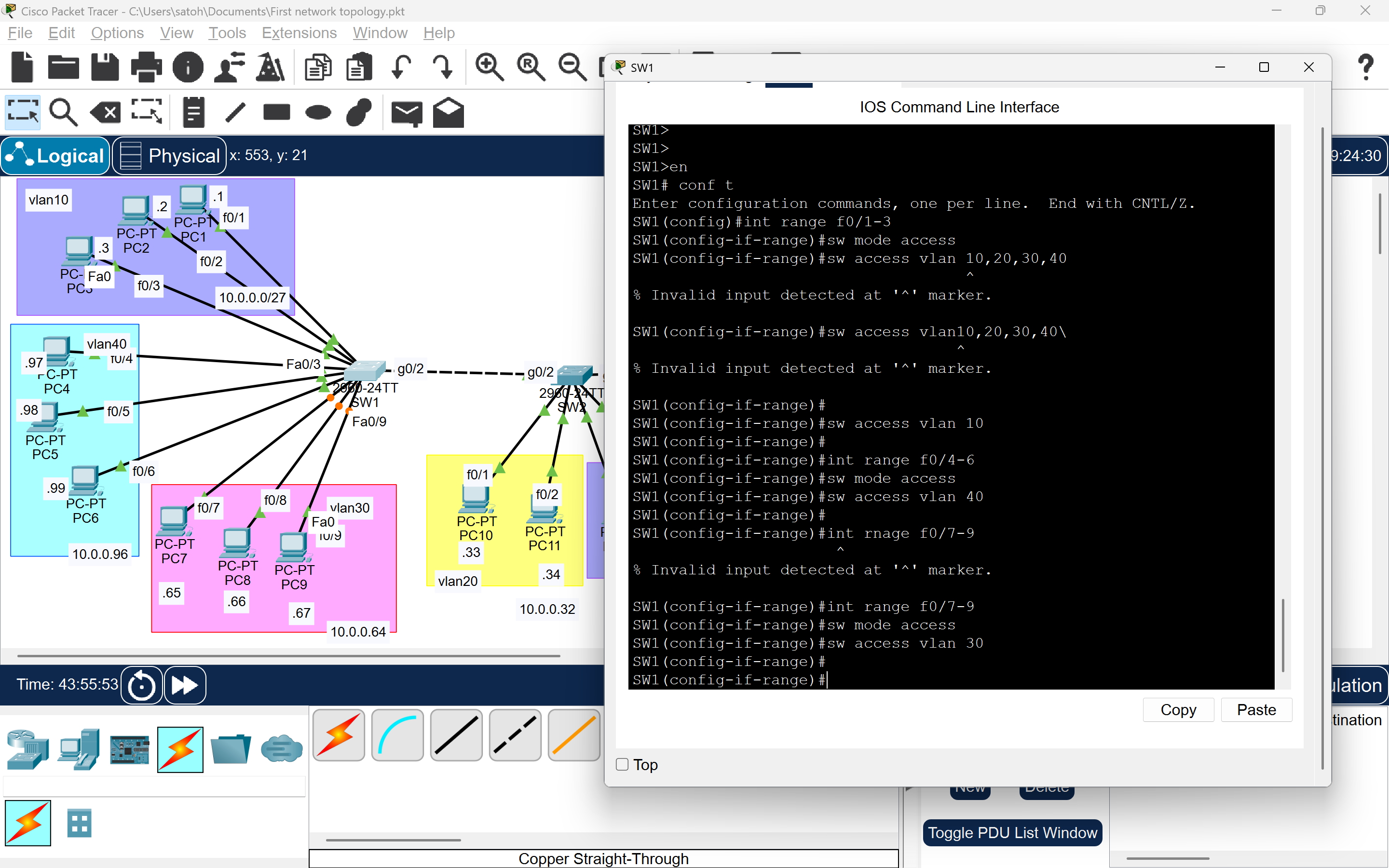
Assign Ports to VLANs: Example for VLAN10 and VLAN40:
SW1(config)# interface range fastEthernet0/1-3 SW1(config-if-range)# switchport mode access SW1(config-if-range)# switchport access vlan 10 SW1(config)# interface range fastEthernet0/4-5 SW1(config-if-range)# switchport mode access SW1(config-if-range)# switchport access vlan 40 -
Configure Trunk Ports (for SW1-SW2 connection):
SW1(config)# interface g0/1
SW1(config-if)# switchport mode trunk
SW1(config-if)# switchport trunk allowed vlan 10,20,30,40
SW1(config-if)# switchport trunk native vlan 1001
Repeat similar configurations for SW2 and SW3, adjusting port assignments based on connected PCs.
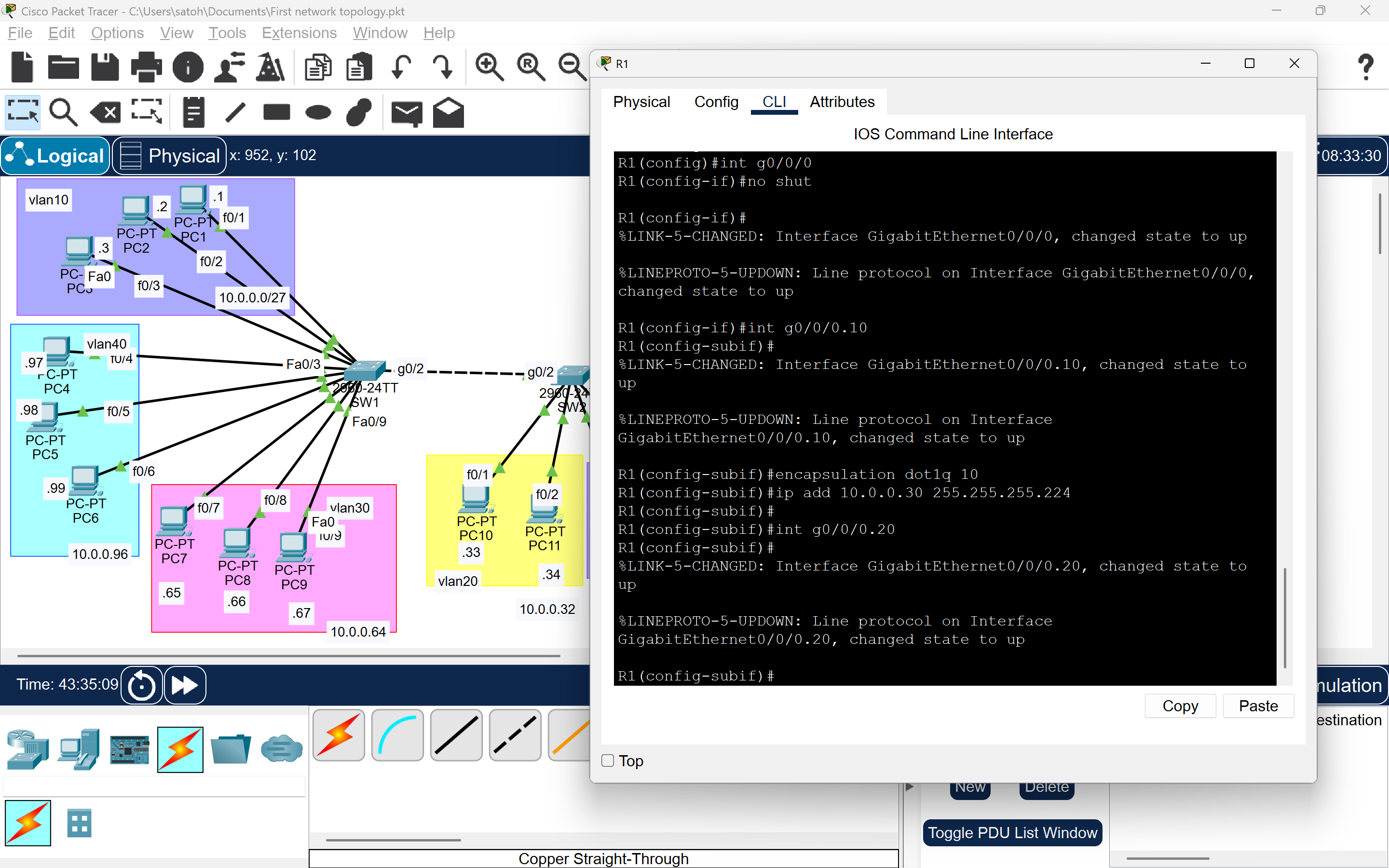
Step 4: Configure Router-on-a-Stick
To enable inter-VLAN routing, configure sub-interfaces on the router.
-
Enable the Main Interface:
Router(config)# interface g0/0 Router(config-if)# no shutdown -
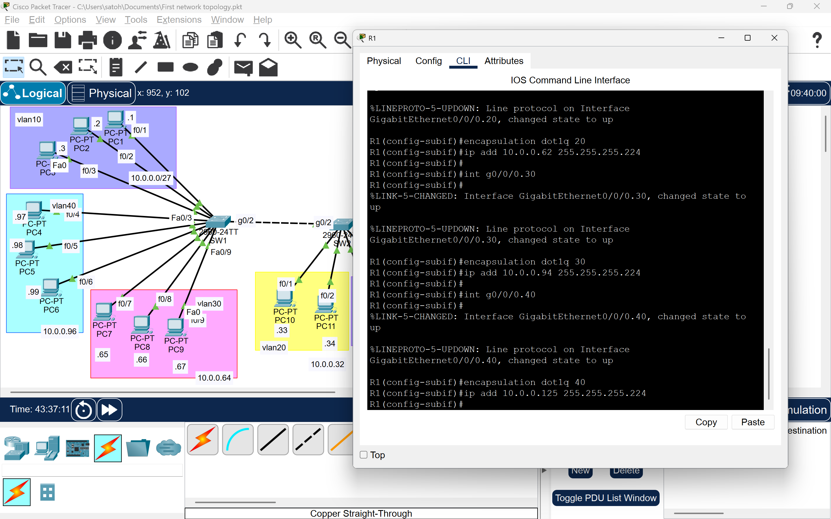
Configure Sub-Interfaces:
Router> enable
Router# configure terminal
Router(config)# interface g0/0.10
Router(config-subif)# encapsulation dot1Q 10
Router(config-subif)# ip address 10.0.0.30 255.255.255.224

Router(config)# interface g0/0.20
Router(config-subif)# encapsulation dot1Q 20
Router(config-subif)# ip address 10.0.0.62 255.255.255.224

Router(config)# interface g0/0.30
Router(config-subif)# encapsulation dot1Q 30
Router(config-subif)# ip address 10.0.0.94 255.255.255.224

Router(config)# interface g0/0.40
Router(config-subif)# encapsulation dot1Q 40
Router(config-subif)# ip address 10.0.0.125 255.255.255.224
Step 5: Test Connectivity & Troubleshooting
Intra-VLAN Testing
- Test: Ping from PC1 (VLAN10, 10.0.0.1) to PC4 (VLAN10, 10.0.0.4) on SW1.

- Issue: If the ping fails, check VLAN assignments on SW1 ports.
- Simulation: Test PC1 to all PCs connected to SW1 to confirm packet forwarding.
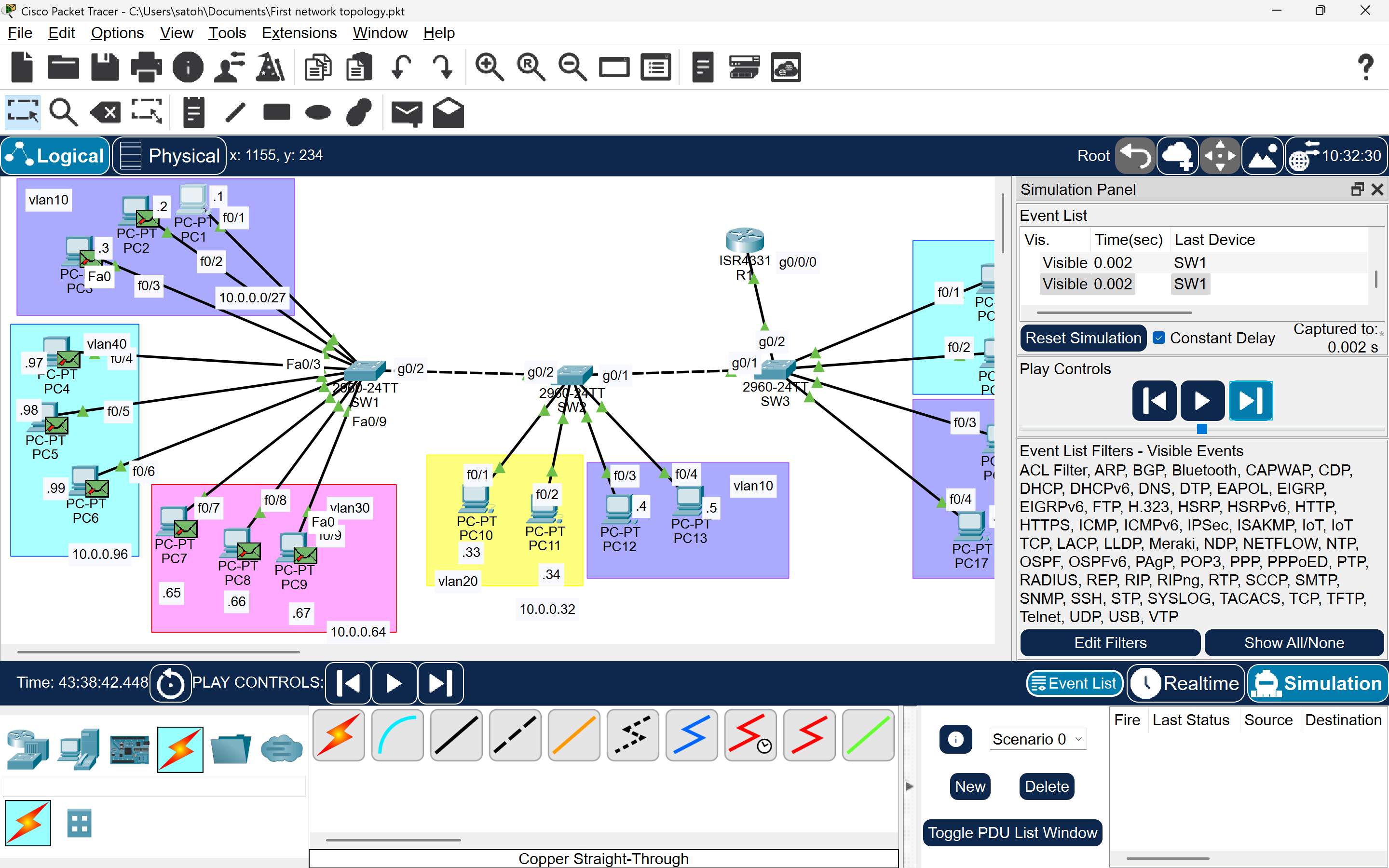
Inter-Switch Connectivity
- Test: Ping from PC16 (VLAN10, SW3) to PC4 (VLAN10, SW2).
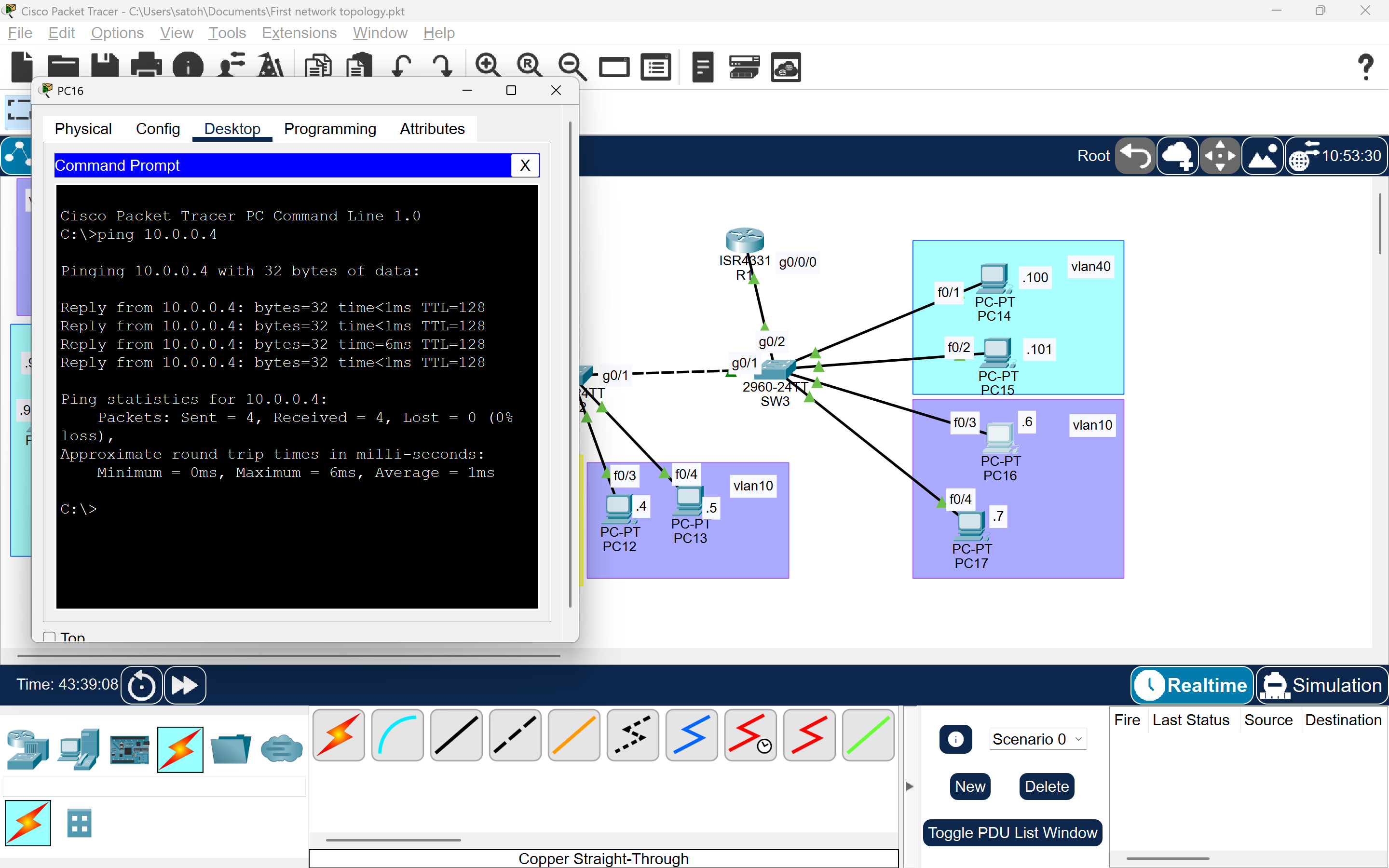
- Result: Successful ping confirms inter-switch trunking.
- Test: Ping from PC16 (VLAN10, SW3) to PC100 (VLAN40, SW3).
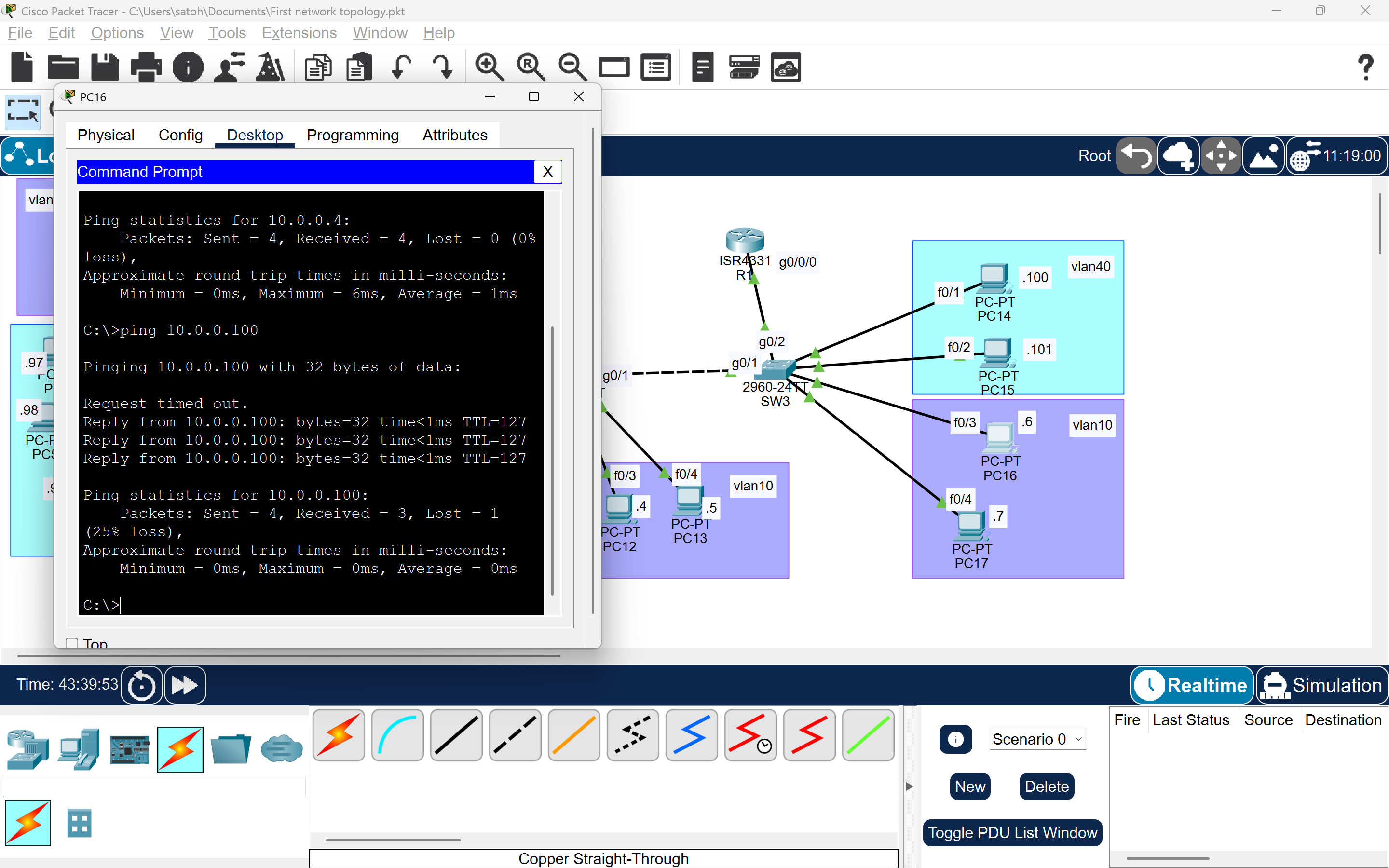
- Result: Successful ping confirms inter-VLAN routing via the router.
Troubleshooting SW1
- Issue: VLAN assignments on SW1 ports were lost, causing ping failures.
- Solution:
- Reconfigure VLAN assignments on SW1 ports.
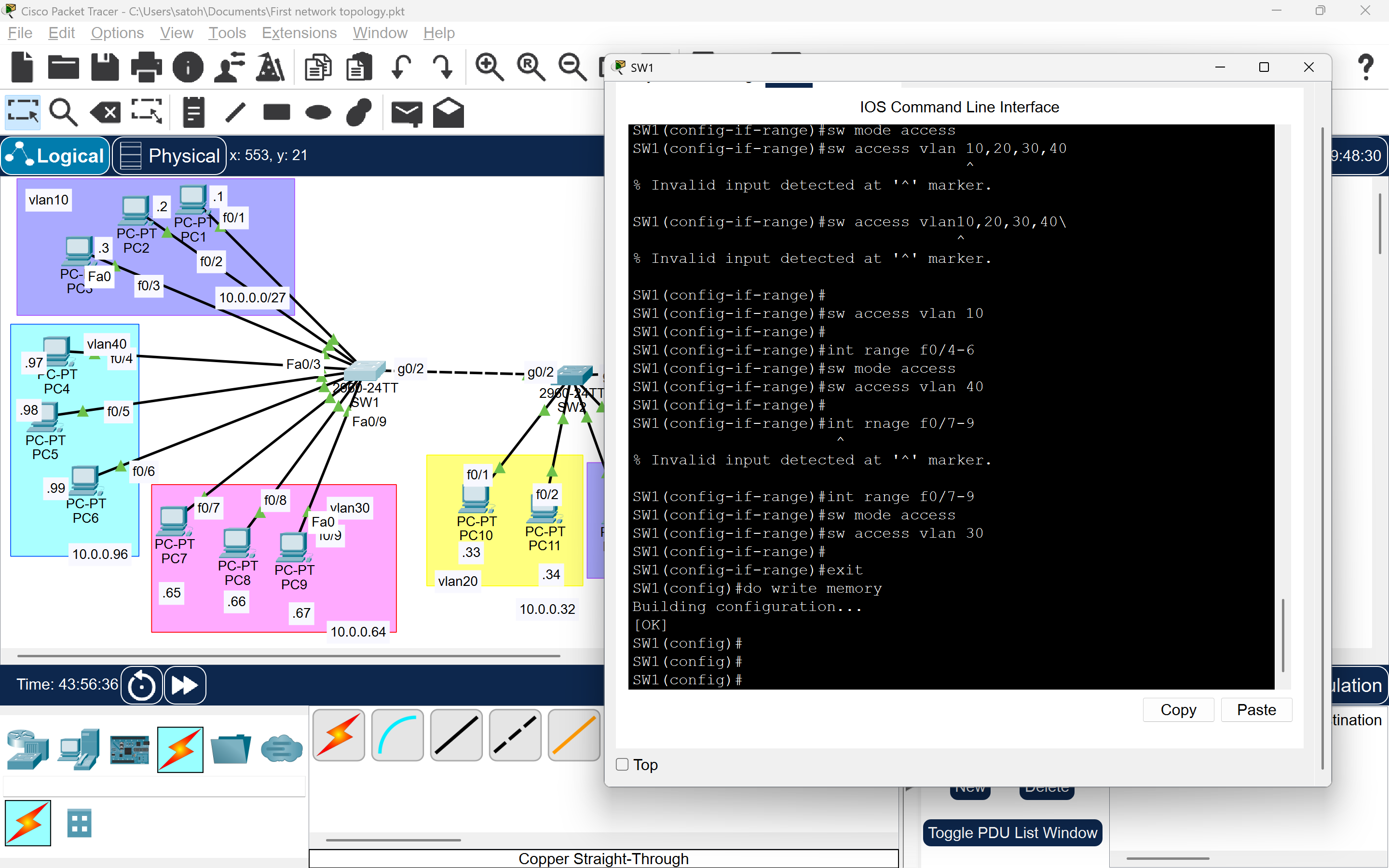
- Save the configuration:
SW1# write memory
Final Ping Tests
- Test: PC16 (VLAN10) to PC1 (VLAN10, via SW1).

- Result: Successful.
- Test: PC16 (VLAN10) to PC65 (VLAN30, via SW1).
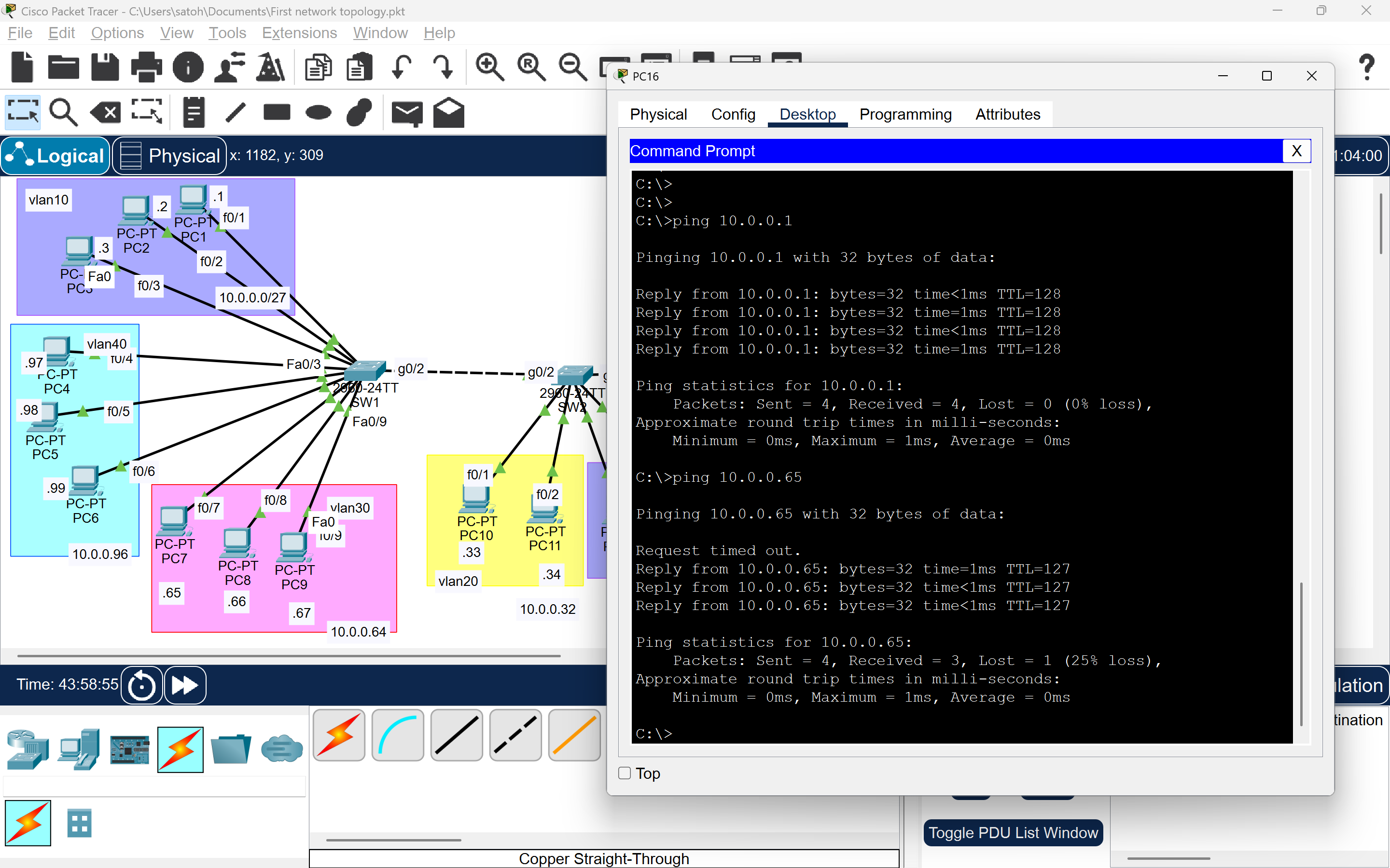
- Result: Successful, confirming inter-VLAN routing.
Key Takeaways
- Verify VLAN Assignments: Ensure switch ports are correctly assigned to VLANs.
- Save Configurations: Always use
write memoryto persist configurations. - Test Connectivity: Validate both intra-VLAN and inter-VLAN communication to ensure a robust network.
Your network is now fully functional! ✅