VLAN Configuration & Trunk Setup Lab
Hi there!
In this lab, I used Cisco Packet Tracer to configure VLANs and trunk ports.
Here’s the network setup and a step-by-step guide.
1, Network Topology
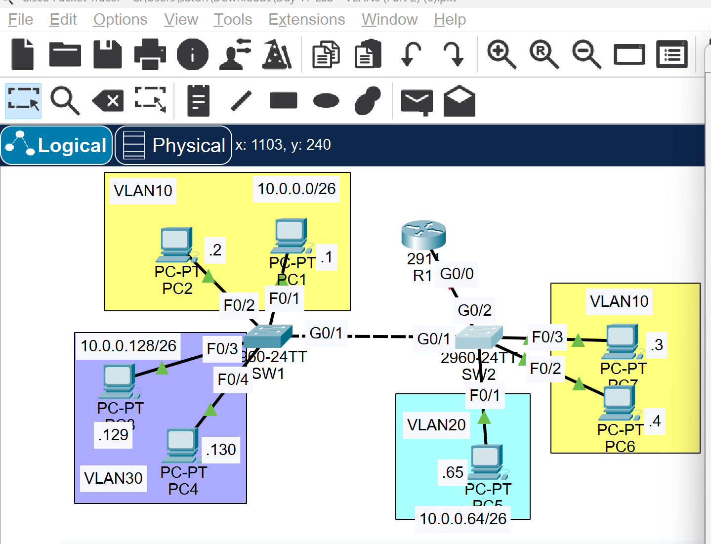
- Configure the switch interfaces connected to PCs as access ports assigned to the correct VLANs.
- Configure the trunk link between SW1 and SW2, allowing only necessary VLANs.
Use an unused VLAN as the native VLAN.
Ensure all required VLANs exist on both switches. - Set up the connection between SW2 and R1 using "Router on a Stick".
Assign the last usable IP address in each subnet to the router's subinterface.
2, How to Configure the Switches
- Create VLANs on each switch using
vlan [ID]in global config mode. - Assign access ports to VLANs:
switchport mode access
switchport access vlan [ID] - Configure trunk ports:
switchport mode trunk
switchport trunk allowed vlan [ID,ID,...] - Set a native VLAN (must be unused):
switchport trunk native vlan [ID] - Configure subinterfaces on the router:
interface GigabitEthernet0/0.10
 encapsulation dot1Q 10
 ip address 192.168.10.254 255.255.255.0
3, Ping Test
Let’s try pinging each PC to verify communication.
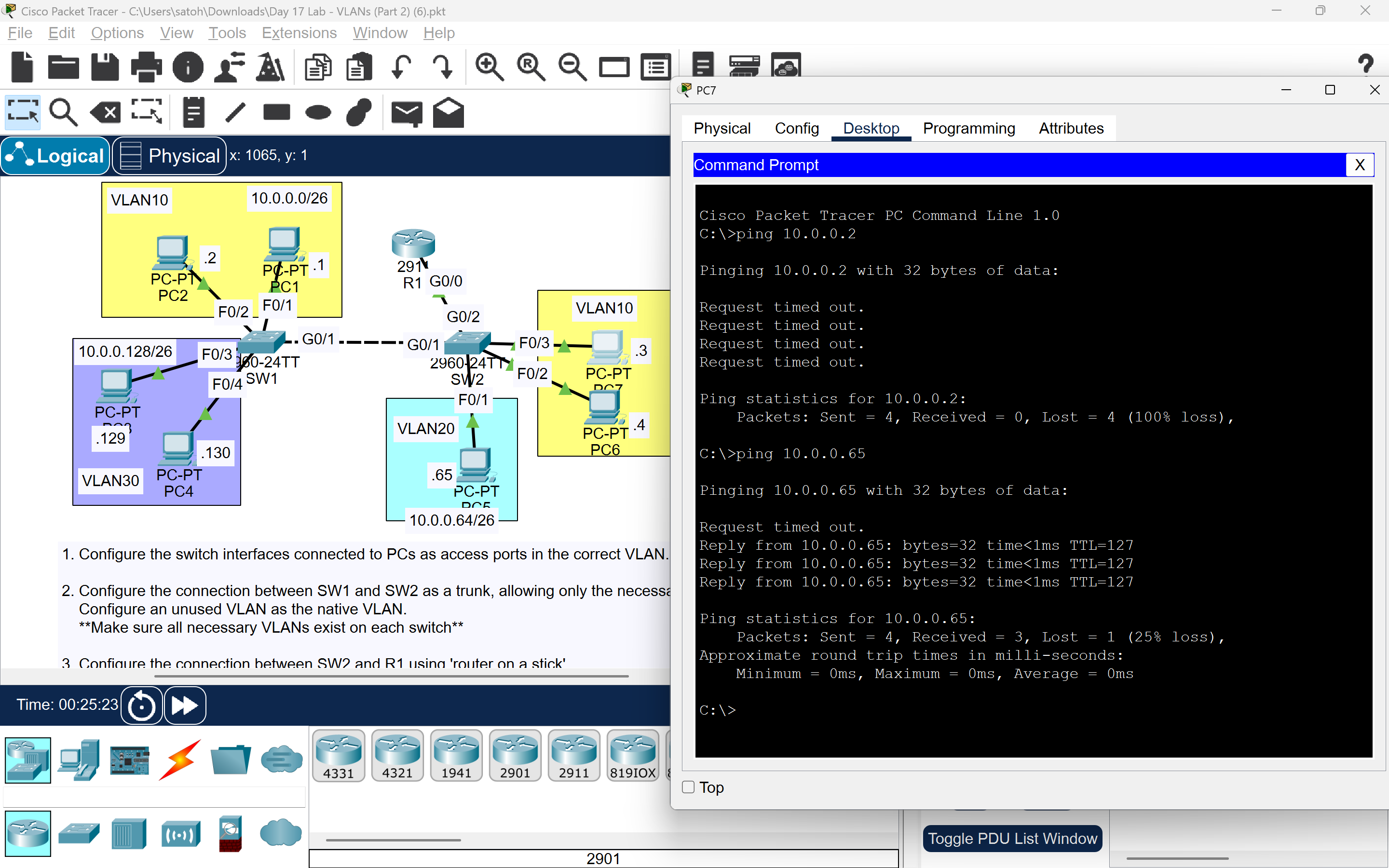
Ping to 10.0.0.65 (PC5) was successful, but 10.0.0.2 (PC2) failed.
This suggests a problem in the trunk link. Let’s inspect the switch config.
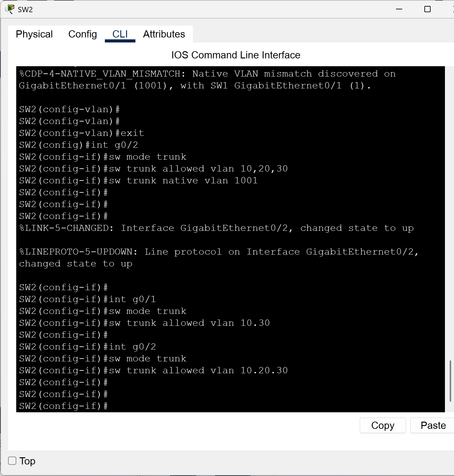
Oops! A syntax mistake: I used a period (`.`) instead of a comma (`,`) when listing allowed VLANs.
That caused the trunk to block necessary VLANs.
Always double-check your syntax!
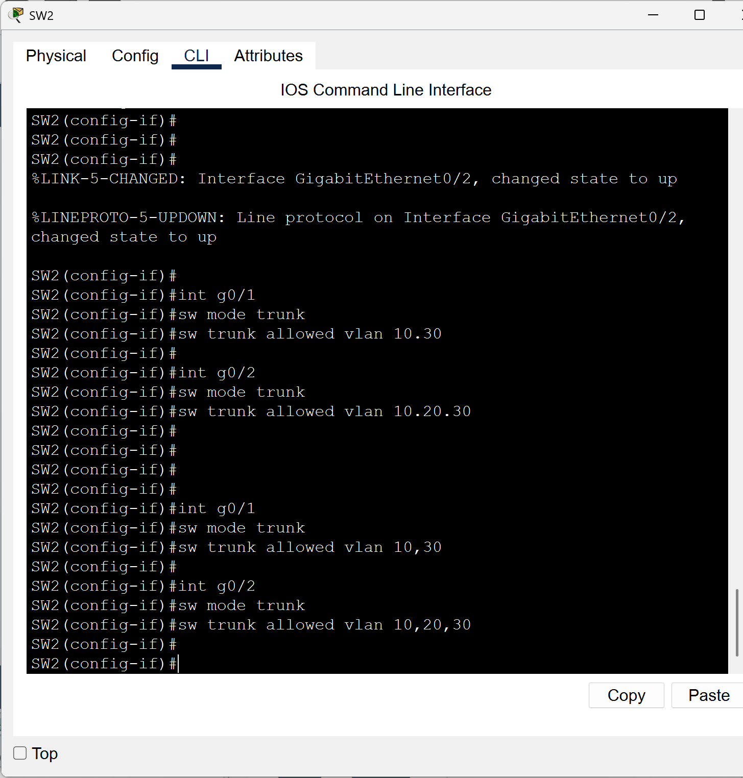
I fixed the trunk config. Time to test again!
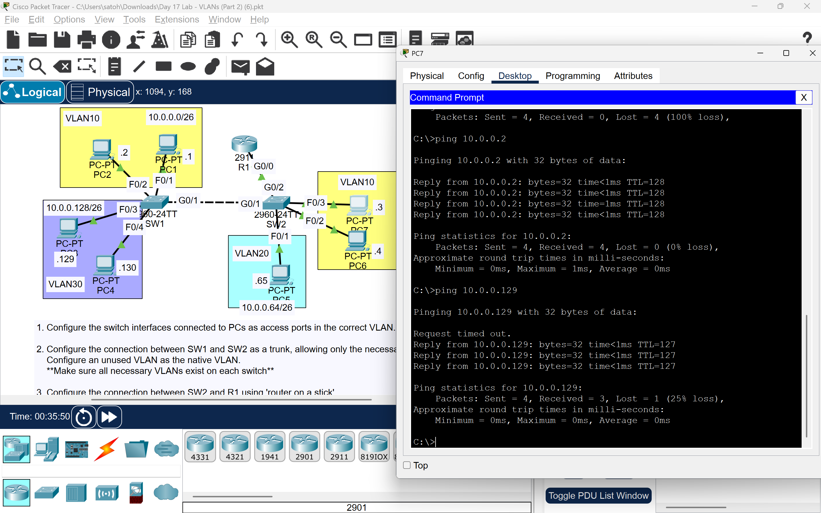
Success! I received replies from PC2 and PC3.
Inter-VLAN routing is now working properly!
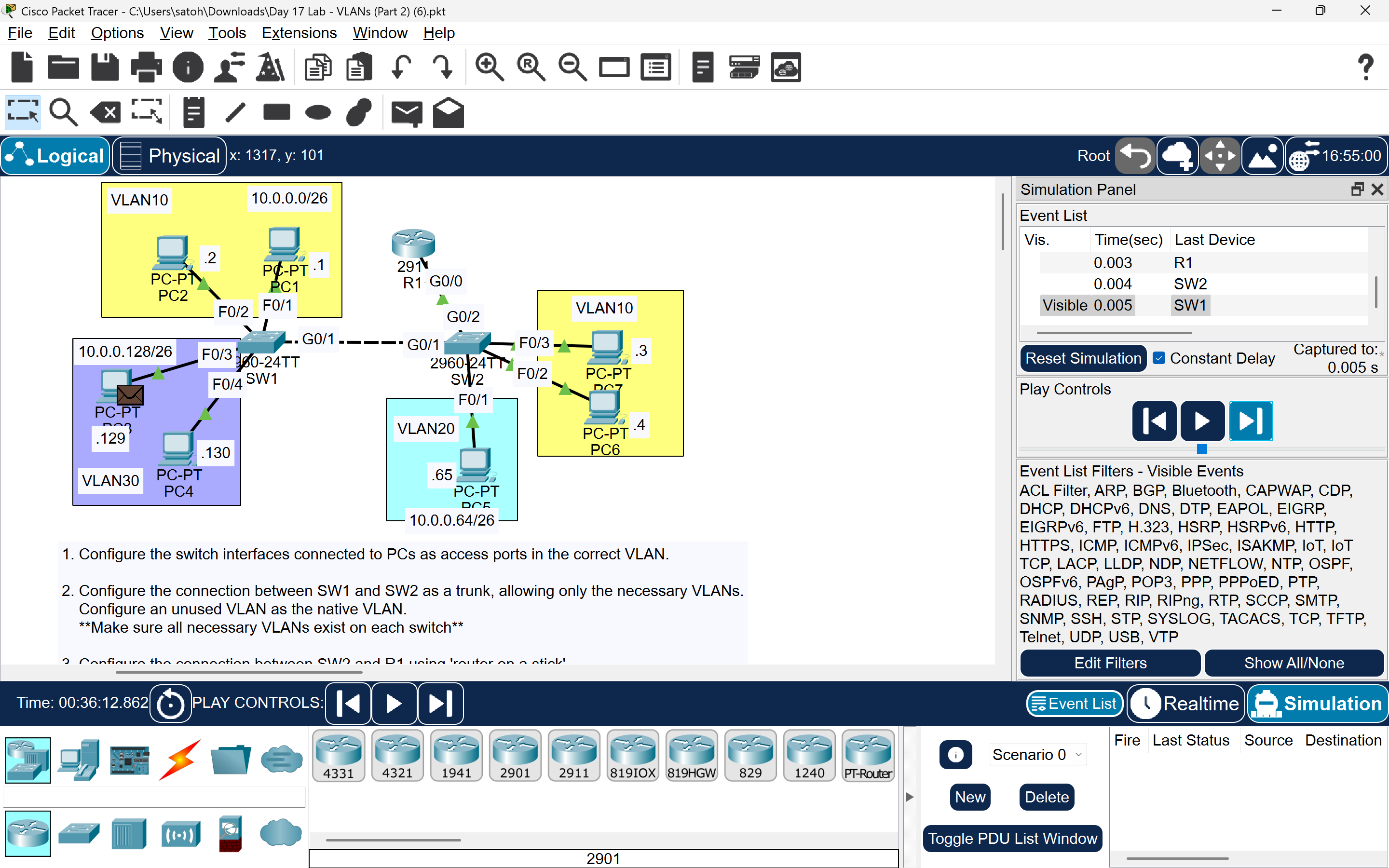
Finally, I used simulation mode to trace the packets visually.
🎉
That’s all for this VLAN & trunking lab!
That’s all for this VLAN & trunking lab!